Sunday, December 28, 2014

Quick update

Just a quick update with some pics from last week. We completed fabrication of the four stainless hinge bases that will be welded to the hull to attach the down rigger poles and the forward support struts for the poles. The base plates are 1/4" stainless so we had to tack them down to some heavier plate to keep them from warping during welding. I found some 3/4" steel rounds that worked well for this. The heat from welding made the side plates want to warp as well. I had to use some threaded rod and bolts to get the assembly straight and square. In the end these came out nice and true, and the hinges operate smoothly with the Teflon washers in place.  We also jigged up the crows nest and tacked the basic structure together. After the holidays, we'll weld up the mast sections and start assembling the mast, cross trees, crows nest, etc. down rigger pole fittings and pad eyes are also ready to be welded up.


Sunday, November 30, 2014

Fabricating the downrigger poles

Spent the past month or so working on the down rigger poles, hinges, and other bits and pieces of the aft mast assembly. I have mostly been tackling this job "an hour here - two hours there", so progress has been kind of slow. I also miss the long daylight hours from the summer- hard to get much done once it gets cold and dark. As soon as I get enough parts cut, fit-up, and prepped, I'll have Romero come by for a day or two to do all the welding. This is all aluminum, fairly thick material, and the end product will need to withstand a lot of stress without breaking. For this, I only trust the professionals to do the hot work. If you refer back to the drawing in the previous post, you can probably figure out which parts are which in these pics. The last photo is the UHMW plastic saddle for the mast support at the back of the wheelhouse roof. More to come...


Sunday, September 14, 2014

Aft Mast Design

While the forward mast will be waiting till next Spring to be created, we have pretty much finalized our aft mast design:


The mast will be stepped on deck, just aft of the wheelhouse and will serve multiple functions: electronics mounting, paravane stabilizing rig support structure, 1000lb boom lift to aft deck (enough capacity to lift our Cummins 6BT main propulsion engine in and out of the boat from a dock alongside), lookout platform 16ft above deck, and about 120 square feet of auxiliary propulsion/steadying sail. In order to eliminate deck interference from wire stays and shrouds, we are using fixed diagonal pipe supports leading to padeyes on the wheelhouse roof. These will work in both compression and tension to support the rig (wire only works in tension). I also will need to add two wires from the mast head to the front of the wheelhouse roof to add necessary support for heavy lifting with the boom. We had the rig modeled, then plugged in different pipe sizes, gussets, etc. until we found a combination that wasn't too crazy heavy but would also not come apart under heavy loading.

After the modeling exercise, these are the scantlings we arrived at. The only changes I made was a switch to sch 80 (heavier wall) for the 2" diagonal mast support pipes, and changing the crows nest railings to 1" to reduce windage and weight. This is view from overhead looking from slightly forward on the stbd side. The wheelhouse and hull are omitted so you have to use your imagination a bit here. The triangular structure on the far (port) side is the paravane rig with hinge pints on the side shell, port side. The stbd paravane pole rig is omitted too.


Here's some pics of the model under load. Blue is low stress (good), red is highly stressed (bad).

First set shows boom lifting 1000 lbs under the following conditions:
straight aft, 45 degrees off center line, and 90 degrees/athwartship


This next set shows the Paravane loading, which puts the most load on the rig (upwards of 5000 lbs) on the paravane down rigger pole anchor points about 16 ft up the mast:


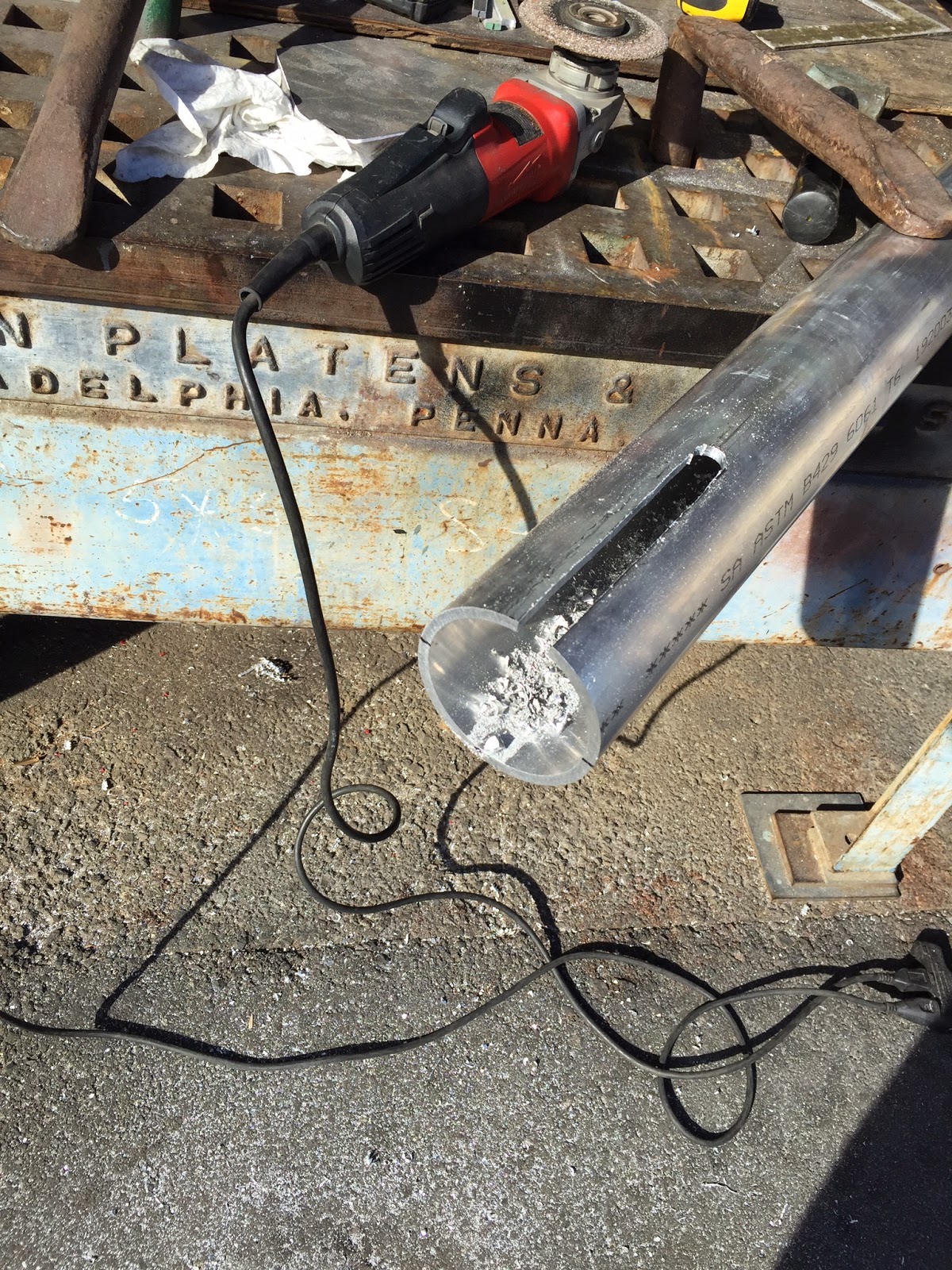
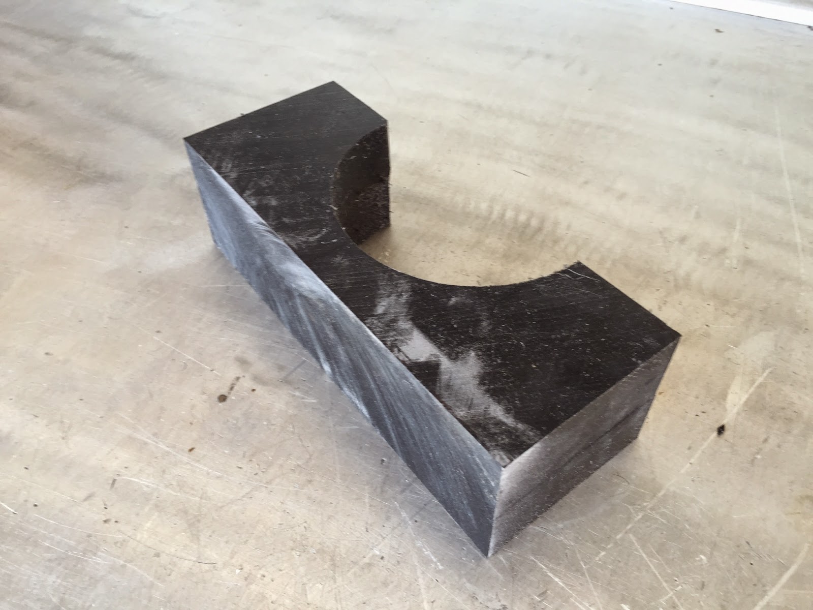
So, the calcs say we're good. I rounded a few things up strength wise to agree with my own "armchair engineering" and now all we have to do is build and install the thing. I started this weekend with the pipe bender at work forming up the upper and lower rails of the crows nest platform. I also came up with materials and design for the paravane downrigger pole hinges. Will be spending some more time in the shop after work this week so that we can start welding stuff together next weekend.


Time Flies...

Just realized that I haven't posted anything in over a month. Time flies when you're busy I guess.
I've been completing a few little loose ends before delving into the aft mast project. More on that in the next post.

The final install of our forepeak and aft cabin bilge level sensors and bilge pump/switch assemblies went pretty well. It was a bit more complicated than the other bilge spaces due to the restricted space and interferences in these areas. Especially vexing was the aft cabin bilge where the access was restricted by the shaft tube, plumbing, and the black-water tank. I ended up installing just the bilge level alarm sensor at the forward (low point) of the bilge, with the pump/switch located a little further aft. This means that the electric bilge pump will probably leave 5-10 gallons of water in the bottom of the bilge. I will be plumbing in pick-ups in each void at some point for the future engine driven bilge pump. The suction for this system will go to the bottom of each bilge so that could take care of any left over water here if necessary. I also had to do some surgery on the cabinet above the aft cabin bilge to install an access hatch in the bottom shelf. This makes for much easier direct access to the aft void versus unscrewing and moving the entire cabinet.


In the engine room, I relocated the gear oil pressure gauge so it is now next to the other engine room gauges instead of it's prior location mounted on the gear. This makes it readable at a glance through the engine room hatch port. I also tee'd off and ran hose up to the wheelhouse to hook up to the mechanical gauge in the dash cluster. This gives two easy ways to watch the gear oil pressure, which is a critical indicator of proper gearbox operation.


While the pathway from the engine room to the wheelhouse was open, I routed the manual activation cable for the engine room fire suppression and hooked up the auto shut-down for the main engine. As it is arranged now, there is an auto discharge that will blow the fire system in the event of high temperature rise in the engine room. You can now also manually discharge the system from the wheelhouse. Either one of these operations will automatically shut down the main engine. This keeps the engine from sucking up all the fire suppression compound. There is a manual bypass switch in the wheelhouse that will allow you to restart the engine after the fire system has discharged. I will probably wire in the diesel furnace into one of the remaining shut off relays in the fire system so the furnace will shut down along with engine in the event that the fire system is activated.